EverFocus RS232 User Manual
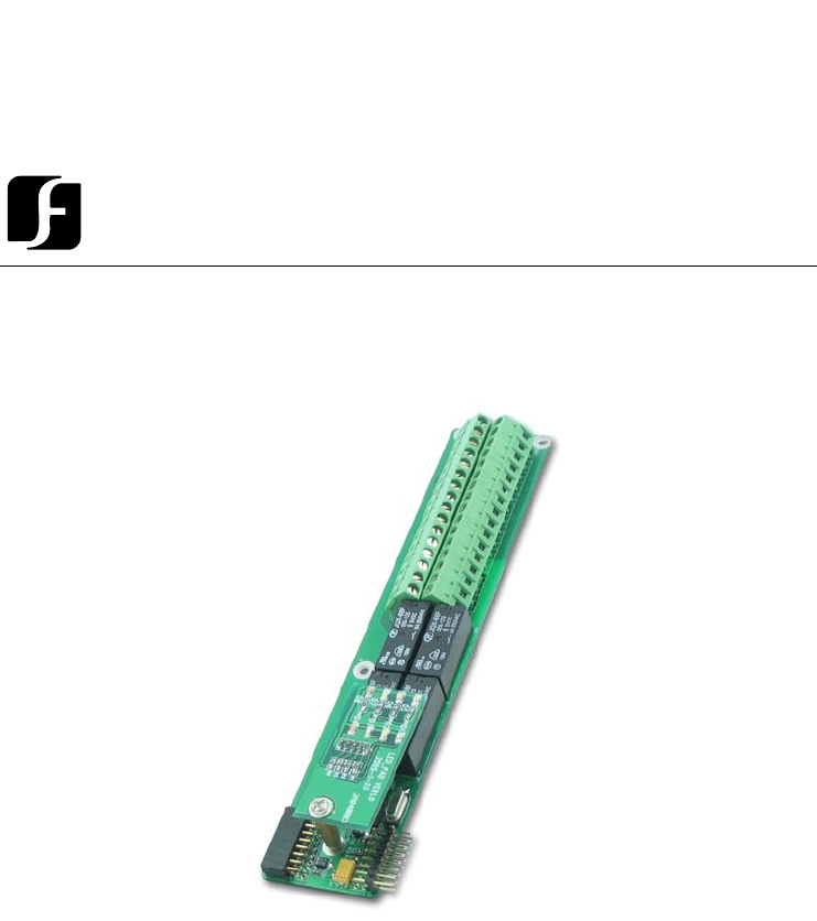
Browse online or download User Manual for Digital Video Recorders (DVR) EverFocus RS232. Door Module for Flex Series Controller EFM-DR-1A
- Page / 17
- Table of contents
- BOOKMARKS
- User Manual 1
- EFM-DR-1A 2
- Instruction Guide 2
- Table of Contents 3
- Product Overview 4
- Specifications 5
- Installing the Door 6
- Module into the Controller 6
- Reader/Door Index Conversion 7
- Terminal/LED Definitions 8
- Door Module LED Definition 9
- Connection to Readers 11
- Connection to Door Lock 12
- Connection to Door Sensor 13
- Door sensor 14
- Connection to Alarm Output 15
- EverAccess 17
Summary of Contents
User Manual DDoooorr MMoodduullee ffoorr FFlleexx SSeerriieess CCoonnttrroolllleerr EEFFMM--DDRR--11AA Volume 1 EverAccess
7 Table 3.2 The definition of LEDs on the door module LED Meaning 1 On indicates the alarm relay #2 energized 2 On indicates reader #2 connected
8 Wiring This chapter will describe, in detail, how to wire the terminals in the door modules. Connection to Readers As mentioned before, each door
9 Wiegand 26 Format 98EverAccessGND+12V45231(17)(18)(19)(20)(21)Reader_Data0Reader_Data1Reader CtrlBrownGreenBlackRedYellow12A B C D E F3G H I4J K L5
10Connection to an Electric Strike 131112(27)(28)(29)V+ V-N.O.COM Fig.4.2 Example for connecting an electric strike Connection to a Magnetic Lock CO
11 10(25)(26)9 Fig. 4.4 Example for connecting door sensor to controller NOTE: Among these four terminals, terminal 9 and 25 are GND, shared by the
12Connection to Alarm Output The alarm module provides 8 alarm inputs and 8 alarm outputs. The user can assign the corresponding relay status to the
Head Office European Office 12F, No.79 Sec.1 Shin-Tai Wu Road,
EVERFOCUS ELECTRONICS CORPORATION EFM-DR-1A Instruction Guide © 2004 Everfocus Electronics Corp 1801 Highland Ave Duarte CA 91010 Phone 626.844.888
Table of Contents CHAPTER 1 Product Overview 1 Features 1 Parts List 1 Specifications 2 CHAPTER 2 Installing the Door Module into the Controller
1 Product Overview The EverAccess® Flex Series controller (part number: EFC-02-1A) incorporates state-of-the-art technology and modular design to pro
2 ¾ 3 mm*4 mm screws (to mount the module to the controller) If an item appears to have been damaged in shipment, replace it properly in its carton
3 Installing the Door Module into the Controller In this chapter, we will introduce how to mount the door module into an EverAccess Flex Series cont
4 2. Secure the module to the controller base board using the three screws (provided in the module package). Reader/Door Index Conversion One EverA
5 Terminal/LED Definitions The definitions of the module terminals are presented in this chapter. Door Module Terminal Definition The terminals on t
6 Table 3.1 the definitions of the door module terminals No Terminal name Function No Terminal name Function 1 Reader1_Data0 Reader 1 Wiegand Data
More documents for Digital Video Recorders (DVR) EverFocus RS232

Related products and manuals for Digital Video Recorders (DVR) EverFocus RS232
 (62 pages)
 (81 pages)
 (39 pages)
 (50 pages)
© 2020, manymanuals.com. All rights reserved. | 1.053 s |
 Manymanuals.com
 Manymanuals.de
 Manymanuals.fr
 Manymanuals.it
 Manymanuals.pl
 Manymanuals.cz
 Manymanuals.es
 Manymanuals-pt.com
Comments to this Manuals